Analytics tool – Antenna testing tutorial
Introduction
Dear GLAMOS friends,
in this step-by-step tutorial we will show you how to utilize GLAMOS Walker and GLAMOS Walk App to test different antennas and find the best one.
Antenna is one of key components in your LoRaWAN and Helium setup. Antenna is a metallic structure that converts current flow generated by hotspots (gateways) or sensor devices to electromagnetic waves, and vice versa. So, it captures and/or transmits radio electromagnetic waves.
Understanding important antenna parameters and specifications helps to choose the best antenna solution for your application. Here are some parameters that affect how antennas will work:
- Voltage Standing-Wave Ratio and Return-Loss
- Bandwidth
- Antenna Efficiency
- Antenna Gain
- Peak Gain
- Average Gain
- Radiation Pattern
All these parameters are affected by antenna design, materials and production technology.
Task of engineer or technician is to find best antenna for specific application. He needs to take in account parameters like:
- height of antenna placement
- area he wants to cover/reach
- is it urban or rural area
- are there some obstacles around – like buildings, forest, hill
- regulations and laws
Today, we will make real field testing to find which antenna best fits for our location. We want to get results what antenna fits our needs, how many hotspots can we reach and can we make some improvements in out setup. Testing will be done with 6 different antennas on 1 location.
Task of engineer or technician is to find best antenna for specific application
Testing overview
- Make sure you’ve set up Walk App and integrated it with Helium. Without integration, you will not be able to store data in Walk App.
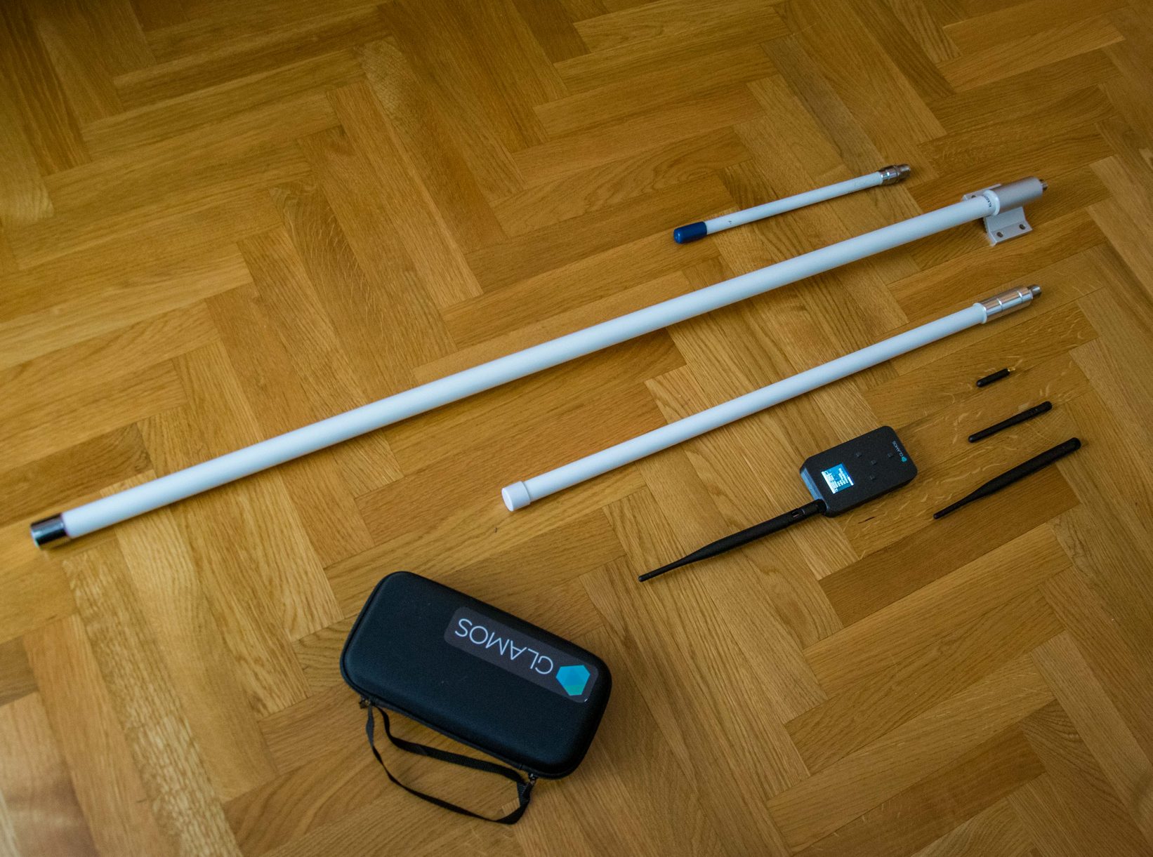
- Prepare:
- Walker
- antennas for testing
- needed antenna adapters/connectors.

Walker has SMA female connector and need SMA male connector on antenna side (not RP-SMA male). Difference between SMA male and RP-SMA male is that SMA male has needle in the middle and RP-SMA male don’t have needle. So for bigger antennas we will use N-type to SMA male adapter/cable.

- Our antennas have gain of 0 dBi, 1 dBi, 2 dBi, 3 dBi, 4 dBi and 5.5 dBi.
When doing testing with different antennas, it is hard to analyze data later because all data become the same. To help you not to take additional notes at what time you used what antenna, we integrated “Antenna type” parameter in device. This parameter will help us to transmit information about antenna from Walker to Walk App.
But it will take too much payload size to transmit text like “5.5dBi” or “my big antenna”. So, we will give alias names (indexes) to our antennas.
| Gain | Length | Index |
| 0 dBi | 5cm | 2 |
| 1 dBi | 10cm | 1 |
| 2 dBi | 21cm | 0 |
| 3 dBi | 30cm | 5 |
| 4 dBi | 50cm | 3 |
| 5.5 dBi | 80cm | 4 |
From now on we will use indexes.
When we say “antenna type 4” that will be same as we say “antenna with 4 dBi gain”.
When we see in Walk App “Antenna: 2”, we will know it is “antenna with 2 dBi gain”.
When we attach antenna with 2 dBi gain on device, we will set up parameter “Type 0” in device menu.

- Make sure you’ve set up MULTIPLE PACKETS in Helium Console. This will allow you to reach to all hotspots in the range. Follow video from 3:07.
https://www.youtube.com/watch?v=pwa3mXbS3x8&ab_channel=GLAMOS
Prepare Walker settings
- For testing we will use SEND MULTI – SAME SF (LOOP) mode.
It will allow us to send multiple time messages, in a row. Using this approach, we will get more realistic and objective results.
When you are sending just 1 message, it is possible that interference occur which can affect signal quality and results. For that reason, we will send 10-20 messages and try to minimize effect of possible bad moments in analytics.
When you are sending just 1 message, it is possible that interference occur which can affect signal quality and results
- For testing Proof-of-Coverage in Helium follow table bellow to set up Spreading Factor.
| Frequency band | Spreading factor |
| EU868 | SF12 |
| US915 | SF9 |
| AU915 | SF9 |
| AS923 | SF9 |
- Now in PARAMETERS change from CONFIRMED to UNCONFIRMED.
- We will do our testing from same location, so in PARAMETERS-POSITION set to any number you want and remember what number what location is. E.g. “Balcony will be number 1”, “Roof will be number 3”, “Basement will be number 7”.
I will test from balcony, I decided it is number 1 so in PARAMETERS-POSITION I will set “1”.
Start testing
- Attach antenna with index 0 on Walker.
- Go to PARAMETERS-ANTENNA and set to “Type 0”.
- Go to SEND ONCE and press SEND until you get “JOIN SUCCESSFUL” message on screen.
NOTE: We need to do this JOIN process just once – after turning device ON. - Go to SEND MULTI – SAME SF (LOOP)
- Set to SF12 for EU868 OR Set SF9 for US915, AU915, AS923
- Set to 10x repeat
- Make sure you hold antenna vertically (pointing to sky). If possible, put Walker on something steady because hands can shake and that can affect results.
- Press SEND and wait that sending is done.
- We will send 20 messages for each antenna (2 times per 10 messages). When sending for 10 messages is done, go back to SEND MULTI – SAME SF (LOOP) and just SEND again.
- Attach now antenna with index 1 on Walker.
- Go to PARAMETERS-ANTENNA and set to “Type 1”.
- Go to SEND MULTI – SAME SF (LOOP)
- Set to SF12 for EU868 OR Set SF9 for US915, AU915, AS923
- Set to 10x repeat
- Make sure you hold antenna vertically (pointing to sky). If possible, put Walker on something steady because hands can shake and that can affect results.
- Press SEND and wait that sending is done.
- Repeat SEND one more time (sending 10 messages 2 times).
- Attach now antenna with index 2 on Walker.
- Go to PARAMETERS-ANTENNA and set to “Type 2”.
- Set to SF12 for EU868 OR Set SF9 for US915, AU915, AS923
- Set to 10x repeat
- Make sure you hold antenna vertically (pointing to sky). If possible, put Walker on something steady because hands can shake and that can affect results.
- Press SEND and wait that sending is done.
- Repeat SEND one more time (sending 10 messages 2 times).
- Repeat process: change antenna – change in PARAMETERS antenna type – SEND 20 messages.
If you change your location of testing (e.g., you go from balcony to roof), go to PARAMETERS-POSITION and change to index (number) of new location. Then repeat testing.
Process is easy: attach antenna on Walker, set antenna index to Parameters, send 20 messages in a row

Analytics
- Now open GLAMOS Walk App and go to Table.
There you can see all your messages from beginning.
Notice Columns Position and Antenna. These are indexes we’ve set in Parameters of device during testing. Value “0” in Antenna column means that message was sent with antenna type 0 attached (that is 2 dBi antenna in this case).
Value “1” in Position column means that message was sent from our location number 1 (that is balcony in this case).
We can analyse data in Table, row by row. We need to compare number of hotspots (gateways) and signal quality (RSSI and SNR) for each message (row) and for each antenna.
To help you make testing faster, we developed Analytics tool.

- Go to Analytics page. Choose device you used for testing and choose time period in which you did testing

- Choose analytics you want to do

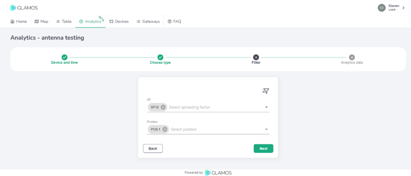
- Choose Spreading factor and Position you want to analyze. We are in EU868 region, we did testing with SF12 so we will choose SF12. Also, we want to analyze antennas from Position 1.
- Aaaand here they are! Results of your testing.
Results
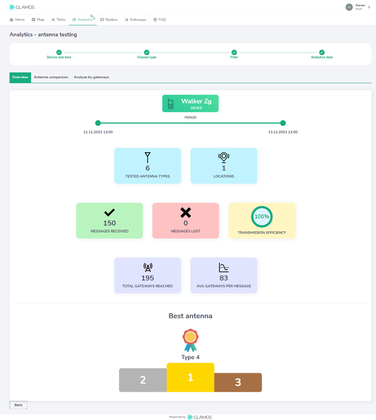
In Overview tab you can see general data about number of sent messages, efficiency and number of reached hotspots. At bottom, you can find result of our advanced algorithm what antenna is the best based on our testing.
The best antenna of our testing is antenna Type 4 – that is antenna with gain of 5.5dBi.
In Antenna comparison tab you can see comparison of all antennas.
Reason why Antenna 4 is the best is that it reached 191 hotspot (gateway) in total, or in average 139 hotspots per each message. That is 23% better than Type 3 and Type 5 which are almost the same.
Type 4 also has the best signal quality (RSSI and SNR) compared to others (more positive is the better).
Worst antenna is 10cm long 1 dBi antenna which reached just 9 hotspots, or average 5 hotspots per message.
On graph are showed lines of Average RSSI for each message. So if 100 hotspots received message, average will be calculated from 100 RSSI values. If we take a look on graph, we can see that Type 4 is not far from Types 3 and Type 5. But we need to know that Type 4 antenna collected 23% more hotspots per message and that were hotspots with lower signal quality (they are far). That degraded final value for Type 4.

If we turn on “gateway count” in graph legend we can visualize how number of hotspots is changing for each message. We sent 40 messages with antennas Type 0 and Type 2 and because of that we have more bars.

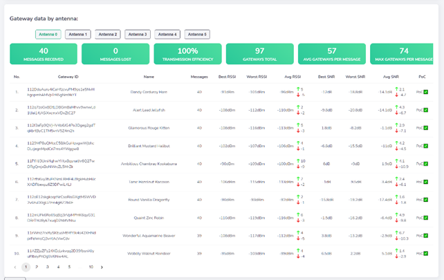
Analyze by gateways tab offers us overview of connection between our Walker and each hotspot.
This allows us to see how some specific antenna communicated with specific hotspot.
In this example we can see that Type 0 had huge oscillations of signal, while Type 4 surpassed all other.

We can also analyze each hotspot (gateway) for each of our antennas. This can help us to see which hotspot gives best communication, which hotspots are not well covered. That allows us to know at what area we maybe will not be able to reach or where reach will be worse.
Conclusion
We did testing with 6 different antennas from 1 location. We can conclude that best antenna is Type 4 5.5dBi antenna, 80cm long, because it has the best signal quality and can reach the most hotspots. Antennas Type 3 and Type 5 are almost the same compared one to other.
Question is do we really need this biggest Type 4 antenna or can we go with smaller antennas Type 3 and Type 5?
In our case, we can go with smaller antennas. For our case, at 7th floor of building, we can reach to enough (100+) hotspots with smaller antennas. There are pros and cons for bigger and smaller antennas.
But we will talk about that in our next blogs, about how to choose antenna for specific location. 🙂
Let us know how you like our tools and feel free to leave us feedback on email.
Yours,
GLAMOS team